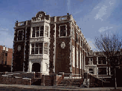
This Blog is to inform all thoses out there about the work and material that is being taught at Technology High School ( to be specfic in the Engineering class). This blog will share all the work and projects that we as students complete and the material that we learn during this time period.
Technology high school

Wednesday, June 15, 2011
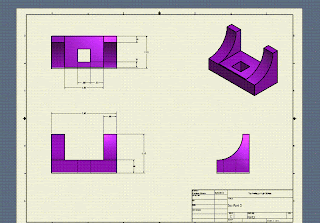
In this activity, we were given the task to create 6 objects on a computer porgram called Inventor. These objects were created and than put on a working drawing that would show how these objects are dimensioned. These working drawings gave all of the measurements and something called the title block. This block was just a desciption of the name of the object, the creater, were it was made and who manged the object.
Friday, March 18, 2011
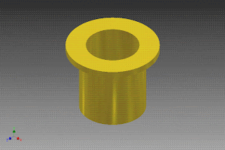
In this project, we were given the task to create different objects based on different tools used in the program called inventor. In this we used a variety of tools. For example, we use extrude, assembly constraints, coil, mirror, fillet, champher, loft and so on. These are some of the pictures of the objects created during the process.
Wednesday, February 9, 2011
The Bverage Container was a project all about innovation. The objective of the project was to take an ordiany white styrophome cup and turn it into our own creation. We could do anything we wanted with it from adding color or ading handles, lids, signs and so much more. The purpose of the project was to show students as well as others that viewed the project what the innovation process was all about.
In my group we came up with idea that the cup should
represent our school-Technology High School. We chose
to add different colors to the cup. We added a purple lid
and a red base. We added a handle to make it easier grip.
The cup also has the school's maskscott on the front of it
along with the intials "THS" which stands for Technology
High School.
after finishing up the project I was happy that I learn was able to learn about the innovation process through this porject. I always wanted to know what happened during that process when a object or item went through it. I learned about the sketching, detailed drawings, labeling, recording and so much more; it answered so many questions i had!
Tuesday, February 8, 2011
"Inventor: Innovation of the
Cup"
This is an example of the continuous of the innovation cup project. After creating the prototype and poster along with the other many things we had to do, used a program that engineers use called "Inventor" where we are able to create 3-dimensional objects or isometric shapes. My cup had different base colors, an handle for a better grip, a lid and a hole at the top for a straw to be placed in to drink out of.
Monday, February 7, 2011
This project was to show how any object has evolved over time. Evolved and has been innovated by any group or type of engineers. This project was used to show how lots of electronics and most technology came to be what it is today through the process of innovation and expound on how different parts of the engineering world is a part of the whole etire process.
I chose this item because it was the best item for this project due to the fact that the cadillac car has been around since the begin of the 20th century. It has undergone many changes inn its look, the way it opereates and so much more.
Sunday, February 6, 2011
Isometric Drawing
These were one of the many sketches we did on isometric drawings. An isometric drawing is a drawing in which a three-dimensional object is represented by a drawing having the horizontal edges of the object drawn usually at a 30 degree angle and all verticals projected perpendicularly from a horizontal base (and all lines are drawn according to a scale) .We were given a list of objects to attempt to draw since it was our first time.
Thursday, February 3, 2011
History of Measurement
The History of Measurement was a project based on the research of measurement; where it begin, who used it first, what tools were first used in the early ages and so on. In this project we were to create a power point on all our research we found which were based on a set of questions we were given to answer, make a book cover or CD cover and also record all our research and all the steps we took to go and complete the project in our engineer's notebook.
The History of Measurement was a project based on the research of measurement; where it begin, who used it first, what tools were first used in the early ages and so on. In this project we were to create a power point on all our research we found which were based on a set of questions we were given to answer, make a book cover or CD cover and also record all our research and all the steps we took to go and complete the project in our engineer's notebook.
Tuesday, February 1, 2011
This project, we were given the task to create combinations which would eventually be made into a prototype. The combinations would consist of 3 cubes, 4 cubes, 5 cubes and 6 cubes. They were made into different componets which would be put together to make three different faces. These faces would be fit togther to fit into a 3 by 3unit cube.
 This cube was my protype. It was used for packaging and advertisment to a puzzle cube design.The cube had to catch the coustumers attention and to follow the required guide lines which were to be fabricated from 27 3/4" hardwood cubes.The puzzle system would contain exactly five puzzle peices.Each indivual puzzle piece must consist of at least three, but no more than six hardwood cubes that are permantely attatched to each other.
Monday, January 31, 2011
Oblique Pictorial
In this lesson we learned how to draw oblique pictorials. There are steps that you have to follow in order to make the object which is the replica look just like the original.
The oblique pictorial starts with a straight- on view of one of the object's faces, which is often the front face angled, parallel lines are drawn to one side to represent the object's depth.We went on to do a activity where we sketched all of the drawing in our engineering notebook
 taking each drawing step by step.
 This cube was the continuous of a combination project which was done on the program cal Inventor used in our engineering project. While in the process of completing this project, we were given the opportunity to create our combinations as well as our cube in 3D form.
 After Creating both my combinations and cube, we create a little video of how the cube is broken up into pieces and then put back together. This picture to the right is what it looks like before it is put to together.
 This was the last step of the Inventor project. This gave the information about the cube- like the title of the project, the author (which was me) and the company (which was my school). It also gave the information about how the cube was made. This is also another picture of what the cube looks like pull apart.
Subscribe to:
Comments (Atom)


